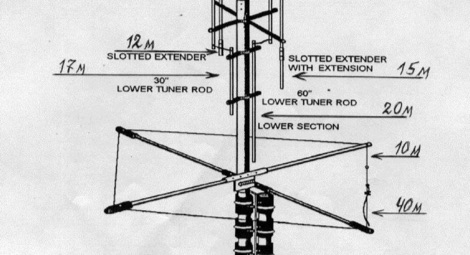
GAP Titan DX Assembly Manual by AE2A (pdf) Download. AE2A Antenna Calculator-Final (xlsx) Download. Wedgefield CERT. These files are free for personal use.
I brought up GAP Eagle antenna for 3 weeks.GAP TITAN DX HF Antenna and Other Antenna's GAP TITAN DX. 8 Band DX Vertical Antenna SPECIFICATIONS 10m 12m 15m 17m 20m 30m 40m and 100 KHz on 80m Height- 25 ft Weight- 25 lbs 'Photo above is just a good photo of a GAP TITAN DX Antenna that I had back a few years when I lived in a limited area for antennas, not my exact antenna'. Am thinking of getting a titan-dx for my postage stamp size lot and would like to get the manual for the Gap quick tilt ground mount to see if it'll meet my needs, but i can't seem to find a copy online anywhere. Email to gap customer support results in crickets. I brought up GAP Eagle antenna for 3 weeks. Results are disastrous. TOS: 1/1 27.985 1/1 25.125 1/1 21. 475 1/1 17.985 1/1 14.480 1/1 7. 325 Completely out of amateur band! Having verified everything I asked via email to gap antenna where could be located the problem. It makes fif. days that I am waiting for the least sign of life of this. GAP TITAN antenna category is a curation of 19 web resources on, Gap Titan DX at DL8RDS, GAP Titan DX Test report, W9GF GAP TITAN DX Antenna Installation. Resources listed under GAP Titan category belongs to HF Vertical Antenna main collection, and get reviewed and rated by amateur radio operators.

Results are disastrous
TOS: 1/1 27.985
1/1 25 .125
1/1 21. 475
1/1 17.985
1/1 14.480
1/1 7. 325
Completely out of amateur band !
Having verified everything I asked via email to gap antenna where could be
located the problem.
It makes fif*** days that I am waiting for the least sign of life of this
society....
If someone already had problems with the Eagle, I thank it by advance to
help me and to give me advices because I have the impression that this
antenna functions as well as the customer service of at Gap antenna!
Best 73 es Dx

Gap Titan Dx Manual Pdf

Gap Titan Dx Antenna Manual
Frank **F6BLP**
Gap Titan Dx Installation Manual
During my research on the MFJ-1798 and other vertical multi-band antennas. I found the GAP Titan. For the most part, it was recommended by most owners. I happened to see a used one for sale at a reasonable price so I figured I'd see what the excitement was all about. After a lengthily battle with the seller who intended to shaft me by not sending the antenna, I finally 'convinced' him to send it. I cleaned it up and installed it only to find it didn't work. After several calls to GAP (great support) and two replacement orders later, I finally got it working. Seems it was either over powered or maybe even hit by lightening. Now I know why the seller didn't want to send it. What a guy. These pictures detail the story. These pictures were taken near the end of September 2004. |
The first thing I found was the capacitor located at the top of the antenna has been damaged. The Titan is good for 100khz of bandwidth on 80m and this cap set the portion of the band that the antenna is resonant on. Customer specifies when ordering the Titan. |
New GAP top Cap installed with electrical tape then double dipped with Plastic Coat. This will help waterproof the connectors. |
Looking up at the completed and working GAP Titan. Maypole 75m wire being pulled away from counterpoise...things are kind of tight for space around here. You can see additional dacron rope guys at mid point of antenna. This is highly recommended. |
Upper GAP section showing rod/GAP positional relationships. Top is at the right. The following pictures are for help with assembly. The Titan manual is a bit lacking when it comes to detailed information on exactly where to place some of the parts. I talked with tech support and asked for the preferred locations. After assembly, I took these photos to document the locations and had tech support view and verify that everything was correct. My hope is that this might help those that are having the same questions I had. |
Additional view of upper GAP section. |
Additional upper GAP section as viewed from the other side. Top is now to the left. |
Lower 'X' section and bottom rods. Notice that all the black wire jumper screws are in alignment (are in the same verticle plane as viewed above) which is really the same horizontal plane when antenna is standing vertically. |
Additional view of the lower 'X' section. |
Additional view from the other side. |
Close-up view of the lower 'X' stand-offs and rods. |
Counterpoise bracket installation location. Mast plate moved all the way up to the joint below the two screws. This is the best location for maximum strength. |
Looking up at the counterpoise bracket and mast clamps. Note: The PVC tubing is something I fabricated as my used Titan was missing the 3 insulating collars. I later purchased the correct replacement collars from GAP. |
Bottom view of the counterpoise bracket assembly. Tower laying on ground is still waiting for the permit. |
Looking up at the Titan. Need to finalize coax installation |
A view of the Titan mounted to the mast and counterpoise along with lower 'X' stand-offs.GAP recommends the coax should exit the antenna at a 30 degree angle. You should also have 12 feet or more of coax lying on the ground on the way to your shack. |
Upper 'X' stand-offs of the Titan. |
Conclusion: After replacing the tuning cap module, missing hardware, and assembling it correctly, it still didn't work. Turns out the internal coax assembly was fried. My guess is the the original owner never had it working correctly and like I stated earlier, either burned it up or it was hit my a lightening strike. Fortunately, this has been my only bad experience buying used equipment from a Ham. I am impressed with the quality and beefy hardware as compared to the MFJ-1798. I didn't get to compare the two against each other but I did favor the Titan for these and other reasons. It does work fairly well and makes a great back-up antenna too so I'm keeping it. Plus in my opinion, it looks really cool! |